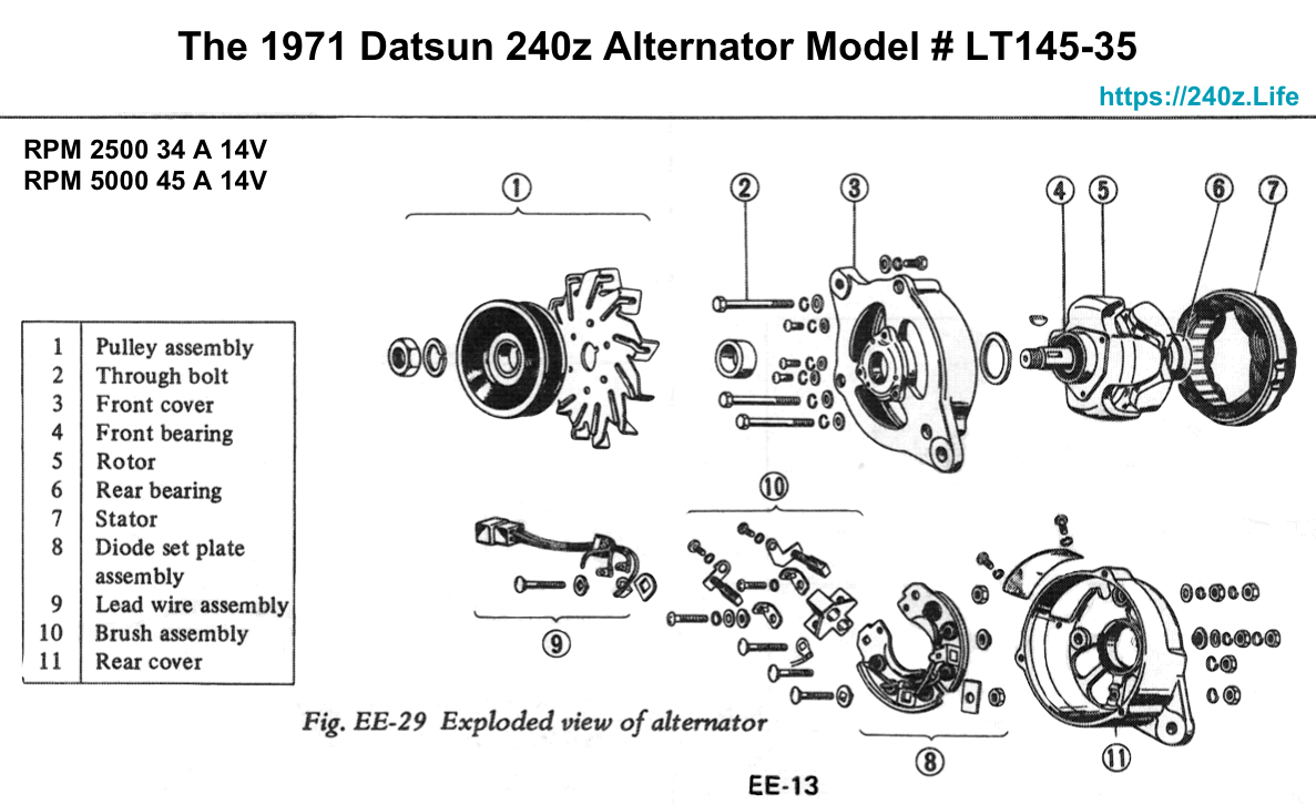
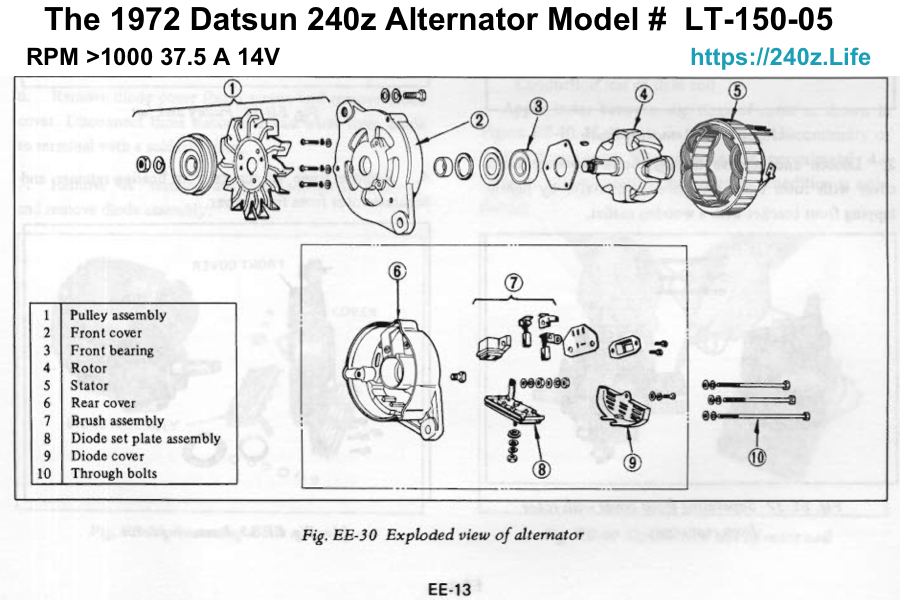
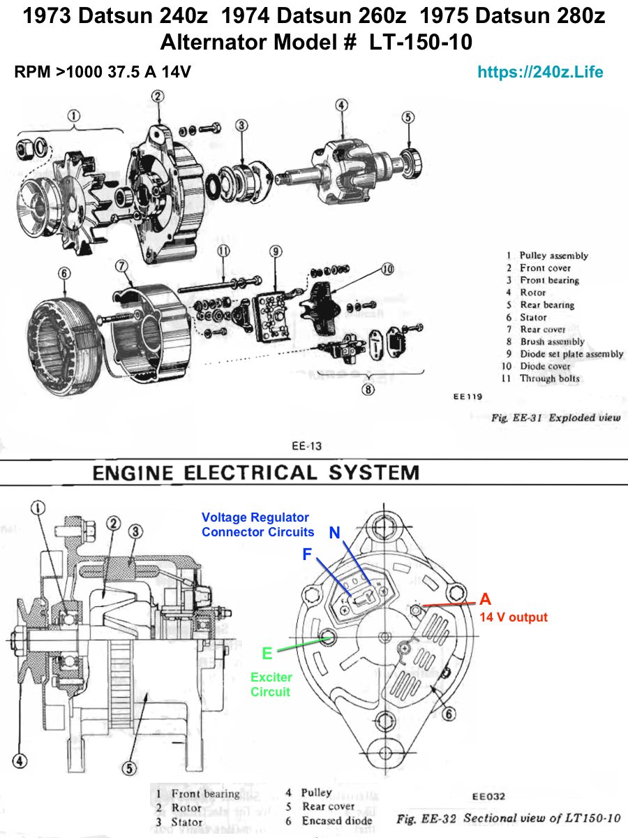
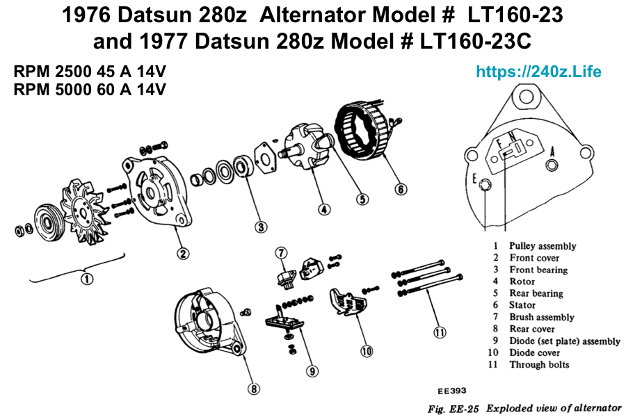
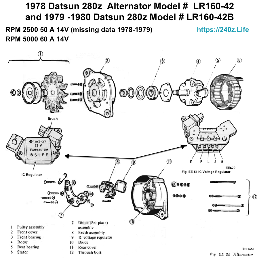
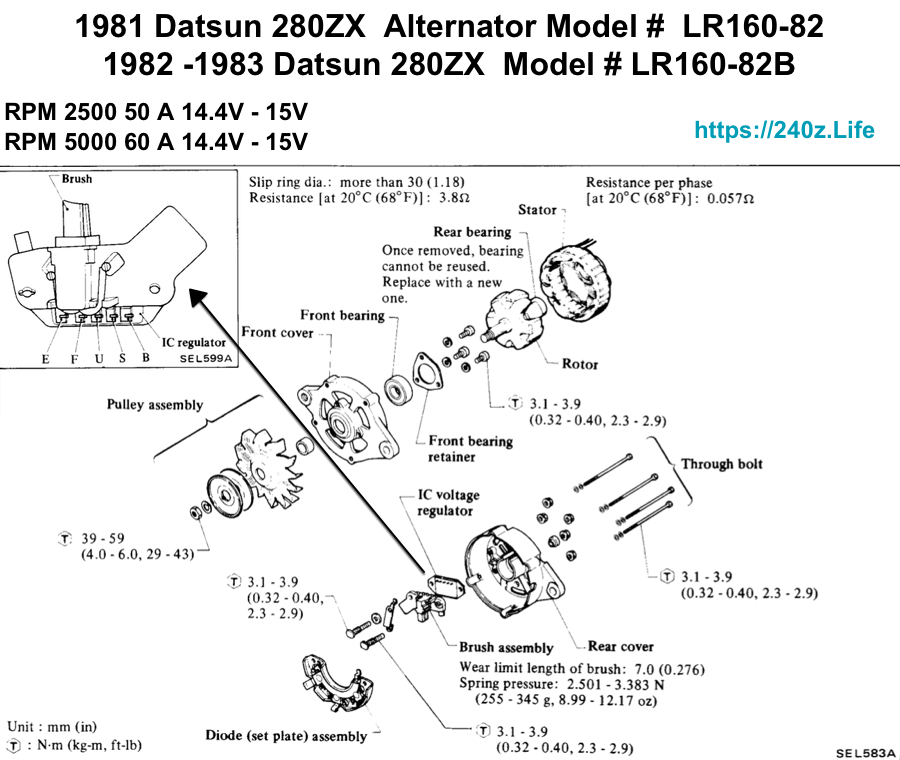
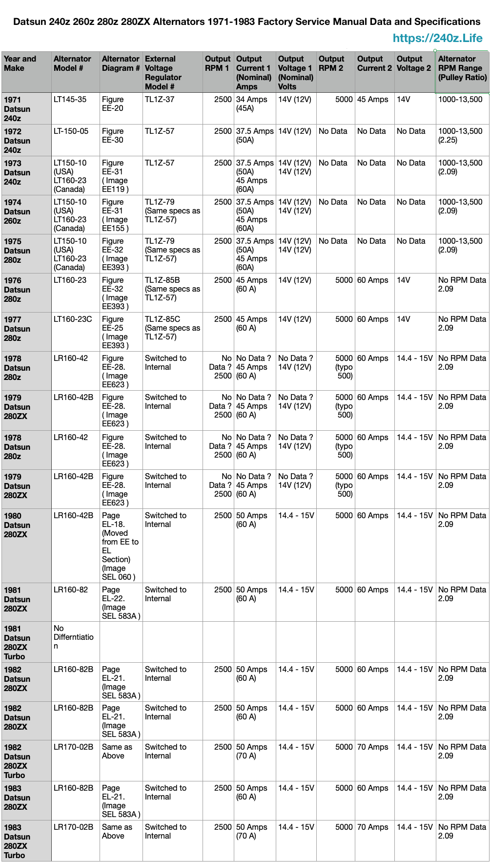
The alternator converts mechanical energy from motor to electrical energy. A Starter converts electrical energy from Battery to mechanical energy to spin gear that engages with the flywheel. The Datsun 240z 260z 280z from 1969 to 1977 used an external voltage regulator, mounted to the passenger fender above the frame rail. There were 4 different models of Alternators. Datsun improved the alternators to produce more current to meet higher demands. The Rotor rotates in the Stator, there are 3 different field windings, producing 3 phase AC current. The current is cleaned up and converted to DC by 3 sets of diodes. The voltage regulator is connected at the T-shaped Terminal. Circuit “F” Field circuit with a White/Black wire and Circuit “N” Neutral Point Voltage circuit with a Yellow wire. The Alternator output “A” Circuit is the White/Red 8ga wire connected to Battery. The Voltage Regulator 12V feed from the fuse box/battery is the voltage input, this is the white wire in the 6P connector from the wiring harness. The Black wires are ground.
Below is a table showing the Data and Specifications from the Factory Service Manuals from Nissan Motor Corp. All images and data are from the Factory Service Manuals
The Voltage Regulators had 5 different models, I think they changed the internal design and the plug design changed 3 times. The Datsun 280z and 280ZX from 1978 to 1983 used an internal voltage regulator.
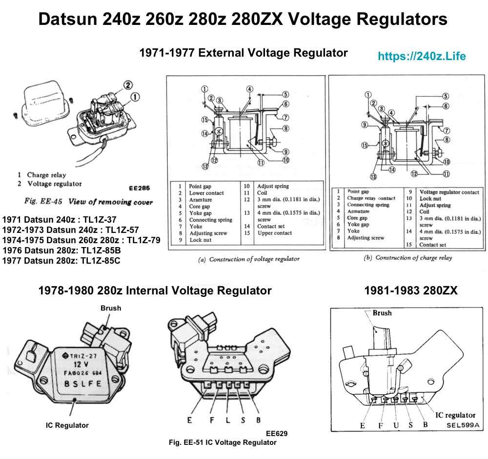
Nissan changed the connector plug 3 times. The wire color for the “IG” Ignition Circuit changed from White/black to White/blue. It is called Ignition Circuit because power goes through the circuit when Ignition is turned to “On” position. This is not the Engine Ignition Circuits for Coil and Distributor. The terminal order goes clockwise. The wiper motor had plug changes also. Nissan was smart and kept the terminal orientation the same.
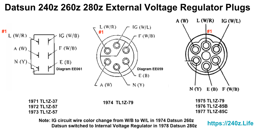
The Alternator and Voltage Regulator work together and charge the Battery. The Datsun 240z 260z 280z from 1969 to 1977 used an external voltage regulator, mounted to the passenger fender above the frame rail. Below are the Internal Circuits. The Alternator and External Voltage Regulator are enclosed in dash lines, this represents the boundaries between the 2 components. The solid lines represent the wires that input the voltage (12V) to the External Voltage Regulator ( White wire 14ga in 6P from fuse box (10A fuse). The thick solid line represents the Output from the Alternator to charge the Battery (+14V), this is the White/red 8ga wire. The lines between both components, “F” (White/black 14ga) and “N” (Yellow 14ga) )circuits, connect the Voltage Regulator directly to the alternator. This is the 2p connector, that plugs into the back of the Alternator. The 1978 – 1983 Datsun 280ZX Internal Regulator circuits are different. This discussion is based on the Datsun 240z Wiring Diagrams and FSM Charging Section.
Alternator and External Voltage Regulator Charging Circuits
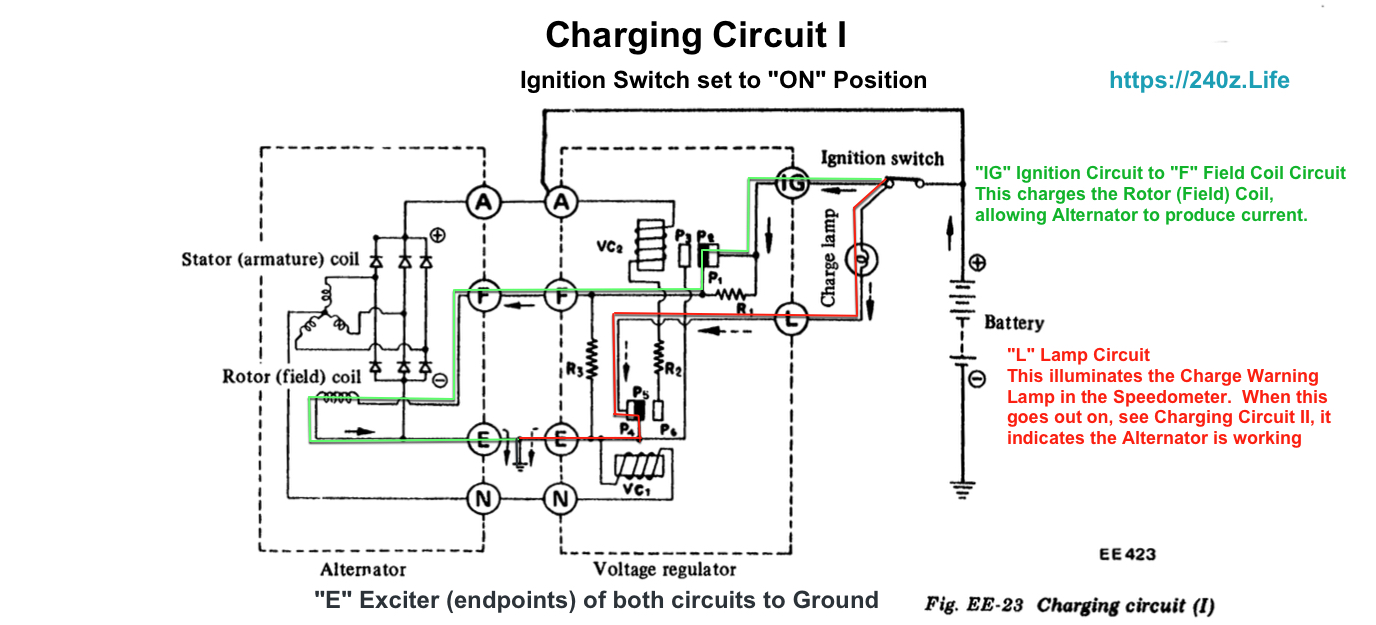
The internal working of the External Voltage Regulator and Alternators are the same from 1971 to 1977. I choose these diagrams for their clarity, Charging Circuit 1 came from the 1977 280z FSM, Charging circuit 2 came from 1976 280z FSM. The circuits for all external voltage regulators are the same. The FSM use a dotted line to define the Alternator and Voltage Regulator seperately.
Charging Circuit Diagram # 1 (1977 Datsun 280z FSM)
There are 2 circuits identified in the Charging Circuit Diagram # 1. Do NOT get confused looking at the wiring diagrams, these circuits are inside the Alternator and Voltage Regualtor. The direct connections from the Alternator and Voltage Regulator are , “E” (Black 14ga) and “F” (White/black 14ga) and “N” (Yellow 14ga) circuits.
The “E” Exciter Circuit, connection between the Alternator and Voltage Regulator (Black Wire) is the “End Point” of the internal circuits and goes to ground.
The “F” Field Circuit, connection between the Alternator and Voltage Regulator (White/Black Wire) is the Field internal circuits and goes to ground.
These circuits are independent and different for the Alternator and Voltage Regulator. “A” circuits represent the + Voltages
Voltage Regulator “A” circuit is the +12V input from the fuse box (White Wire), 10 Amp fuse. “A” circuits represent the + Voltages. Alternator “A” circuit is the +14V output that goes to the Fuse Box (White/Red Wire), 20 Amp fuse.
Reference Charging Circuit (1) Fig. EE-23 Diagram # EE423 1977 Datsun 280z FSM by Nissan
Ignition Key in the “ON” position
First circuit
The “L” Lamp circuit is the Internal circuit in the Voltage Regualtor, This light goes on when the key is in the “On” position. The “E”Exciter circuit is an external connection from the Alternator and Voltage Regulator and allows the current to go to ground. The current path goes from the +12V Battery through Ignition Switch to Charge Warning Lamp “L” circuit, then to the contact points (lamp side Contact Point P4 to the movable contact point P5, then the current flows to the Voltage Regulator external terminal “E” (Ground). This turns the Charge Warning Lamp “ON”.
Second circuit
The current path goes the +12V Battery through the ignition switch to “IG” to “F” to “E” (Ground) in the external voltage regulator. The “IG” circuit is the Internal “Ignition” circuit in the Voltage Regulator, it provides current from the Battery to primary side contact point “P1” to movable contact point “P2”, then to the Voltage Regulator external terminal “F” Field Circuit. This is connected to the Alternator circuit “F” Rotor (Field) Coil circuit. The current flows to the Rotor Field Coil, which excites (charges the coil) the current flows to the “E” end circuit in the Alternator to Ground. This charging allows the Alternator to produce current, through windings in the Rotor (Field) coil and the Stator (armature) coil. The Armature rotates in the Magnetic field of the Rotor ( Field/ Magnetic Field which is charged..having current though it). The diodes in the Alternator convert the current from AC to DC. The brushes ride on the armature end and actually transfer the energy to the “A” Alternator circuit.
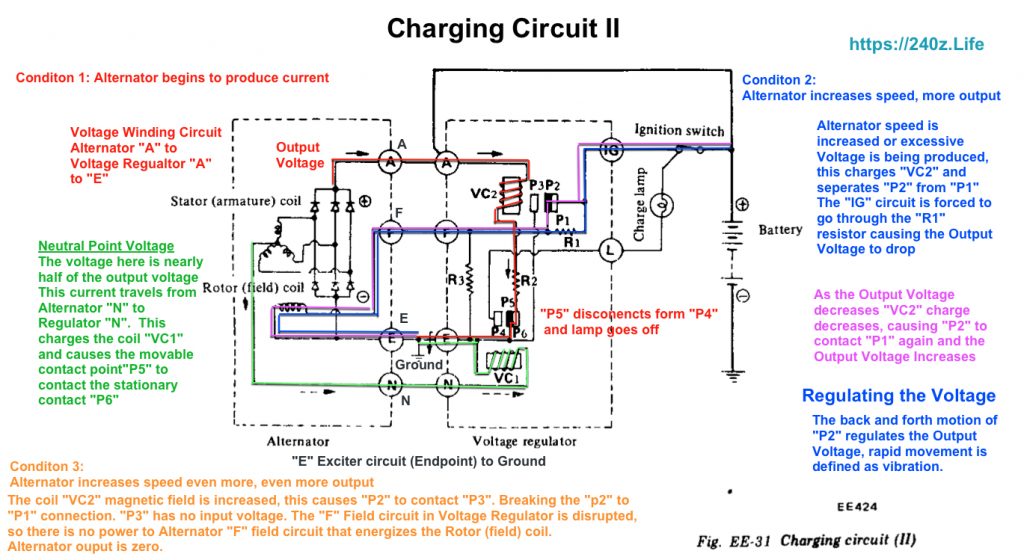
Reference Charging Circuit (2) Fig. EE-31 Diagram # EE424 1976 Datsun 280z FSM by Nissan
First circuit
The engine is running and the Alternator begins to produce current. Remember the Alternator Rotor (Field) Coil is charged and the Charging Warning lamp is ON.
Three phase alternating current is induced in the armature, and then is rectified by the diodes. The rectified direct current outputs to Alternator terminials “A” and “E”.
The “Neutral Point Voltage”, is nearly half of the output voltage. The current exists the Alternator “N” circuit and enters the Voltage Regulator “N” circuit.
The current charges coil “VC1” and cause the movable contact point “P5” to contact stationary contact point “P6”. The Charging Warning Light goes OFF, indicating the alternator is charging.
Second circuit
Condition 1: Alternator Begins to produce current
The output voltage current travels from the Alternator “A” circuit to the Voltage Regulator “A”. The Output to Battery is solid black line, this is not inside the dotted lines representing the Alternator or Voltage Regulator, this Wire is White/Red 8ga.
The Neutral Point Voltage, charges the “VC1” coil ( Green Circuit), this causes “P5” to contact “P6. This allows Voltage Regulator circuit “A” to go to ground. completing the circuit (Red Circuit)
Condition 2: Alternator increases speed and starts to produce more current
Regulating the Output Voltage
Alternator speed is increased or excessive Voltage is being produced, this charges “VC2” and seperates “P2” from “P1”. The “IG” circuit is forced to go through the “R1” resistor causing the Output Voltage to Drop
More current to “VC2” coil causes “P2” and “P1” to seperate forcing current to flow through Resistor “R1” this decreases current to Rotor (Field) coil. This causes the output voltage to drop, as the Output Voltage decreases the coil “VC2” charge decreases and “P2” contacts “P1” again and Output Voltage Increases.
Condition 3: Alternator speed increases even more, where excessive voltage is produced.
The Alternator Output increases to the point where the coil “VC2” has enough force to have movable contact point “P2” contact stationary contact point “P3”. There is no input voltage to the “F” Field circuit in the Voltage Regulator, so the “F” circuit in Alternator receives no current, the Rotor “Field” coil is not charged. Alternator Voltage Output is Zero.
I would like to add that the mechanism of changing circuit paths using charged coils to create a magnetic field, to move a contact… to complete a circuit, is how a modern Relay works.
These are the exploded views of the Alternators from the Factory Service Manuals .
